Alternator wiring problem
Moderators: FORDification, Thunderfoot
-
logger536
- New Member

- Posts: 4
- Joined: Sun Apr 08, 2018 8:13 am
Alternator wiring problem
I am having a problem with my alternator on my 67 V-8 F100. I put a new alternator on the truck, and seem to be missing the wire for the stator connection. The problem is I cant see where the wire would have been, no broken wires, ect. I look at the wiring diagram and it shows the stator going to the voltage regulator, however on mine that wire is there, it goes from the regulator into a 4 pin connector and then into the harness to the firewall. That part of the harness is still wrapped and appears to be intact. I found several new ones, however the connector is different than mine. All the diagrams I see are the same, yet different than what I have. What am I missing? I see in the regulator schematic the stator wire goes to ground, can I ground the stator wire coming off the alternator along with the ground for the alternator?
-
Ranchero50

- Moderator

- Posts: 5799
- Joined: Wed Nov 08, 2006 7:02 pm
- Location: Maryland, Hagerstown
- Contact:
Re: Alternator wiring problem
Google around. If memory serves the wiring was different depending on what instrument cluster the truck had. Idiot light went one way and the gauge went another. There are wiring diagrams under the main Fordification site. Have you looked at those?
'70 F-350 CS Cummins 6BT 10klb truck 64k mile Bahama Blue
Contact me for CNC Dome Lamp Bezels and Ash Tray pulls.
Contact me for CNC Dome Lamp Bezels and Ash Tray pulls.
-
Lee
- New Member
- Posts: 215
- Joined: Sat Nov 27, 2004 10:04 am
- Location: Lacey, Washington
Re: Alternator wiring problem
Hi,.
First off, I would not ground the Stator connection. Diagram shows this connection goes to the Regulator on a White wire with a Black stripe. Inside of the Regulator, this connection then goes through an Inductor and then to ground.
Looking at the 4 pin connector that connects to the Regulator,... are there wires on all 4 pins? You should see: a green w/red stripe, a Yellow, a White w/black stripe, and a White.
So please confirm that you are having a charge problem.... what is the voltage reading at the battery while engine is at idle?
Lee
-
logger536
- New Member
- Posts: 4
- Joined: Sun Apr 08, 2018 8:13 am
Re: Alternator wiring problem
Lee,
I only have 12 to 12.5 volts across the terminals when the engine is idling. The regulator has 4 wires going in to the plug that goes on to the regulator. The diagrams that I have found talk about a charge indicator light yet I have gauges in my instrument cluster. I just hooked it all back up without the stator terminal connected to anything and no charge. I am ready to just rewire the whole thing following the diagrams I found here. I'm not finding any aftermarket wiring looms that have the same 4 post plug like I have.
I only have 12 to 12.5 volts across the terminals when the engine is idling. The regulator has 4 wires going in to the plug that goes on to the regulator. The diagrams that I have found talk about a charge indicator light yet I have gauges in my instrument cluster. I just hooked it all back up without the stator terminal connected to anything and no charge. I am ready to just rewire the whole thing following the diagrams I found here. I'm not finding any aftermarket wiring looms that have the same 4 post plug like I have.
-
Lee
- New Member
- Posts: 215
- Joined: Sat Nov 27, 2004 10:04 am
- Location: Lacey, Washington
Re: Alternator wiring problem
Hi,
It may be a pain but I would probably start removing the wire lomb (or electrical tape) covering the wires starting at the connector at the Regulator working towards the engine and see if you can find where the White w/black strip wire goes.
I understand the alternator not charging without the Stater connected as this connection provides the ground reference (thru an inductor) for the Stater winding's.
Do you have a voltmeter? If so, you could remove connector from Regulator and ohm out the White w/black strip wire in the plug. Then reconnect the plug, crank engine and see if you get a voltage on the pin. If it isn't shorted to ground, and there is no voltage on the pin, theoretically, you could splice in a connection to the "S" connection on the alternator.
Concerning the Charge light, the diagram shows that the green w/red strip wire at the regulator would have connected to it... not the White w/black strip Stater wire. but since you have gauges anyway I guess it's a moot point.
Hope this helps,
Lee
-
Thipdar
- New Member
- Posts: 84
- Joined: Fri Apr 09, 2010 8:26 pm
Re: Alternator wiring problem
What you are describing sounds correct to me.logger536 wrote:I am having a problem with my alternator on my 67 V-8 F100. I put a new alternator on the truck, and seem to be missing the wire for the stator connection. The problem is I cant see where the wire would have been, no broken wires, ect. I look at the wiring diagram and it shows the stator going to the voltage regulator, however on mine that wire is there, it goes from the regulator into a 4 pin connector and then into the harness to the firewall. That part of the harness is still wrapped and appears to be intact. I found several new ones, however the connector is different than mine. All the diagrams I see are the same, yet different than what I have. What am I missing? I see in the regulator schematic the stator wire goes to ground, can I ground the stator wire coming off the alternator along with the ground for the alternator?
There's a reason that your VR connector doesn't use all four wires.
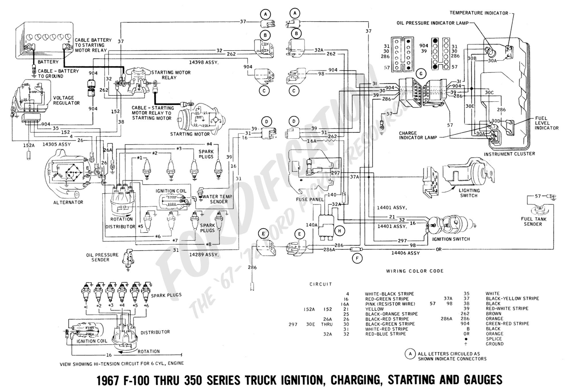
Take a look at this diagram: http://www.fordification.com/tech/wirin ... gauges.jpg
Follow wire # 904 from the VR through the two connectors, through the Instrument Cluster Connector and look where it goes: the "CHARGE INDICATOR LAMP" -- which your truck DOES NOT HAVE. For a truck with idiot lights, that is the most obvious place to test to see if the alternator is charging.
If your truck has gauges, it won't have a wire at this position of the VR connector. Idiot lamps are either off (0v) or on (12v). Ammeter Gauges, on the other hand, need to indicate a range of current (not voltage), from negative through positive. You might be able to wire up a circuit to do both, but it's not worthwhile; the different functions were implemented with different circuitry and there is no provision for measuring current inside the Voltage Regulator.
If your truck has gauges, you don't need to hook up the Stator stud. You need Ground, Field and Battery. The moldings on the ends of those cables should make it so that they only hook up one way (that's an assuming your cable ends are terminated that way, and based on what's in my 1970). IIRC, the molding on the ends of the cables should include a position for the Stator if your truck uses idiot lights.
BTW, the Stator connection doesn't go directly to ground in the VR; it goes to a coil, which connects to ground on the other side of the coil. It would be a bad idea to connect the Stator stud directly to ground. If that was really necessary, it would be done automatically within the alternator.
If you re still having a charging issue, it's somewhere else.
-
logger536
- New Member
- Posts: 4
- Joined: Sun Apr 08, 2018 8:13 am
Re: Alternator wiring problem
Now that makes sense to me, I will have to check that out in the next few days.
Thanks
Thanks
-
Nappy22
- New Member
- Posts: 2
- Joined: Thu Apr 19, 2018 9:12 am
Re: Alternator wiring problem
I would like to carry on with this post. I have a 1971 F100 with gauges. But I think it came with idiot lites. Any ways I have new alternator and volt. Reg. But still not charging. I have bat volt at Alt. And reg. All the time on yellow wires. Have 12 volts at green/red (904) with key turned on. And have continuity between reg. And Alt. On orange wire. Could it be because I don’t have a lite hooked up to 904. Which I believe runs to Alt. Lite.
-
Thipdar
- New Member
- Posts: 84
- Joined: Fri Apr 09, 2010 8:26 pm
Re: Alternator wiring problem
Please start a new thread for this.Nappy22 wrote:I would like to carry on with this post. I have a 1971 F100 with gauges. But I think it came with idiot lites. Any ways I have new alternator and volt. Reg. But still not charging. I have bat volt at Alt. And reg. All the time on yellow wires. Have 12 volts at green/red (904) with key turned on. And have continuity between reg. And Alt. On orange wire. Could it be because I don’t have a lite hooked up to 904. Which I believe runs to Alt. Lite.