|


|

|
|
|
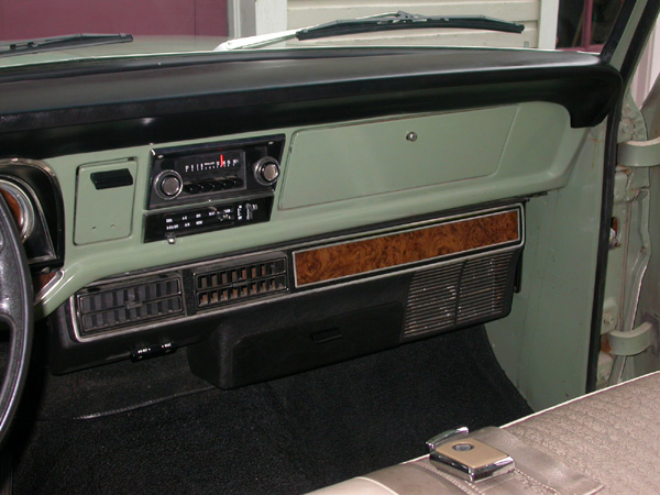
Factory A/C Control Cable Hookups |
|
 |
|
This is just a simple photo-tutorial showing the proper
hook-up points for the four selector cables that control the
factory suitcase-style air-conditioner/heater combo. This
style of A/C is the ONLY factory setup...all other styles
are aftermarket add-ons, and are not covered here, because
they do not use the in-dash control cables.
Fig. 01 |
 |
|
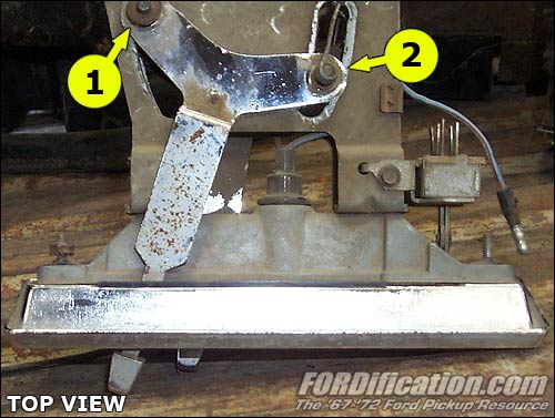
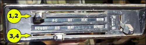
There are four selector cables which extend from the
dash-mounted control panel to various places on the A/C
unit. For ease of identification, I've labeled these cables
1-4. Cables 1 and 2 are connected to the top slider on the
control panel, Cables 3 and 4 are connected to the lower
slider, as shown below. |
Top
View
(Fig. 02) |
 |
Front
View
(Fig. 03) |
 |
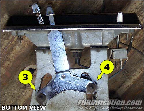
Bottom
View
(Fig. 04) |
 |
| |
|
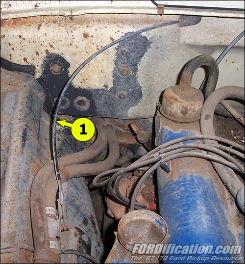
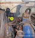
Cable #1 |
|
Cable #1 extends from the left side of the top slider (in the
heater/AC control panel) as shown in Fig. 02, through the
firewall, and connects to the heater control valve (water valve)
in the heater hose, inside the engine compartment.
Cable length: app. 36-3/4" |
(Fig. 05) |
| |
|
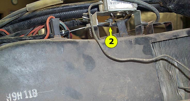
Cable #2 |
|
Cable #2 extends from the right side of the upper control panel
slider as shown in Fig. 02 to the bottom of the thermostatic
switch, mounted on the right/front top of the A/C unit.
Cable length: app. 31-1/2" |

(Fig. 06) |
| |
|
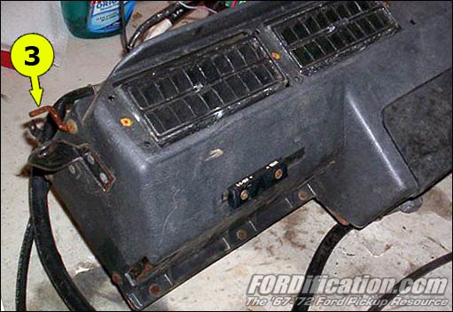
Cable #3 |
|
Cable #3 extends from the left side of the lower control panel
slider as shown in Fig 03 to the heat/defrost door lever,
located on the left side of the A/C unit.
Cable length: app. 18-1/4" |

(Fig. 07) |
| |
|
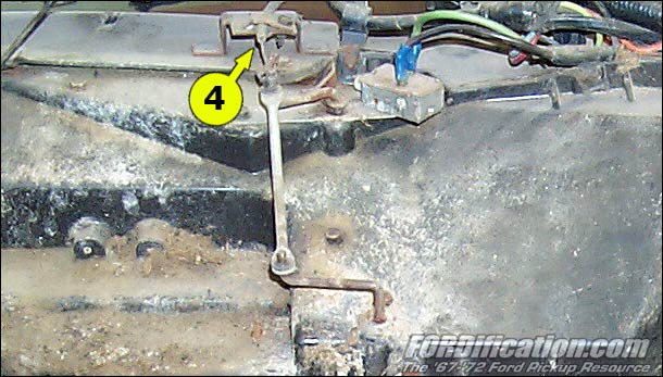
Cable #4 |
|
Cable #4 extends from the right side of the lower control panel
slider as shown in Fig. 03 to the A/C door lever, located on the
right/rear of the A/C unit. This also actuates the A/C
compressor's clutch switch.
Cable length: app 31-1/2" |

(Fig. 08) |
|
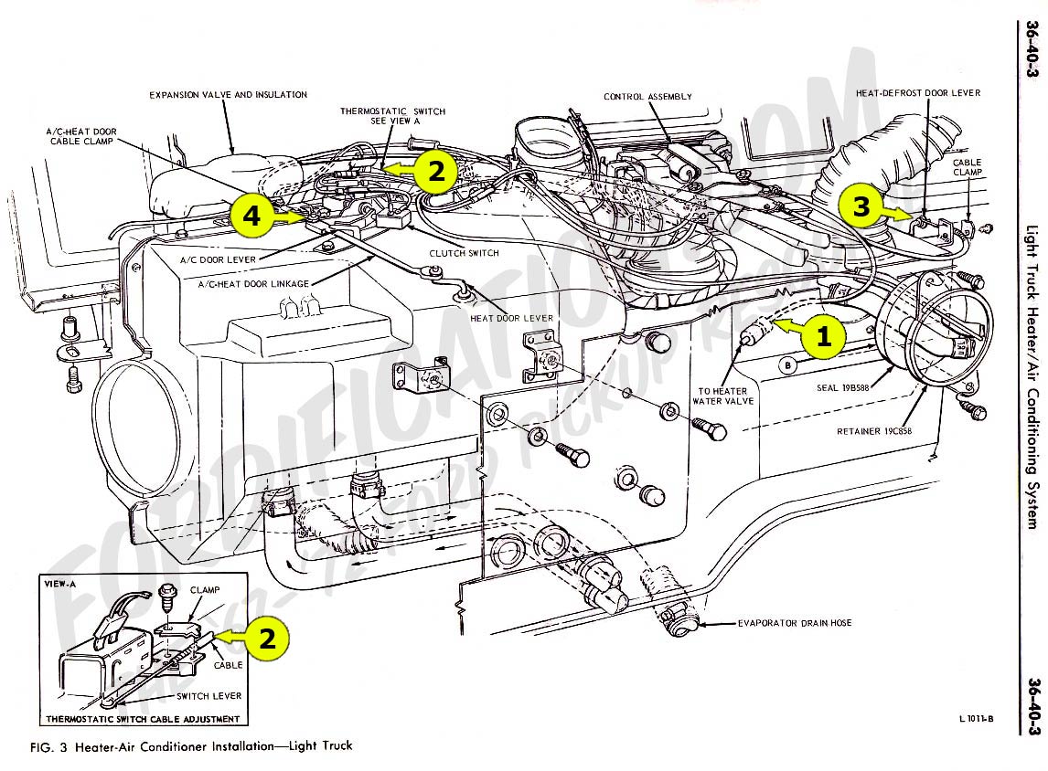
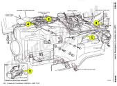
I've also labeled the cable hook-ups on this heater/AC diagram
from the Ford Master Parts catalog, which might help give you a
better visual reference.
(Fig. 09) |
 |
|
 |

Want to link to
this site? Please save this banner to your hard drive to place on your
webpage.
The correct link to use is
http://www.fordification.com
|