Hey Lance! Oh I see what you mean; thanks for pointing it out. Yeah I have no idea why it doesn't have it. I suppose I could ask John and see if there's some specific reason for that.
Thanks Lance!
-Robroy
FE and T18/C6 mounts from Autofab, plus frame alignment.
Moderators: Ranchero50, DuckRyder
-
robroy

- 100% FORDified!

- Posts: 3768
- Joined: Sun Jul 06, 2008 4:36 pm
- Location: California, Salinas
-
DuckRyder

- Moderator

- Posts: 4941
- Joined: Mon Jul 19, 2004 3:04 pm
- Location: Scruffy City
- Contact:
Re: Upgraded FE motor and transmission mounts from Autofab.com
Those are nice mounts...
The reinforcement/gusset is strange, I'm no engineer but it seems like the drivers side would be in shear/strech and the passenger in compression?
I'd like to hear the explanation if for no other reason that to assure myself that its intentional and not an .
.
The reinforcement/gusset is strange, I'm no engineer but it seems like the drivers side would be in shear/strech and the passenger in compression?
I'd like to hear the explanation if for no other reason that to assure myself that its intentional and not an
Robert
1972 F100 Ranger XLT (445/C6/9” 3.50 Truetrac)
"An unarmed man can only flee from evil, and evil is not overcome by fleeing from it." -- Jeff Cooper
1972 F100 Ranger XLT (445/C6/9” 3.50 Truetrac)
"An unarmed man can only flee from evil, and evil is not overcome by fleeing from it." -- Jeff Cooper
-
robroy
- 100% FORDified!
- Posts: 3768
- Joined: Sun Jul 06, 2008 4:36 pm
- Location: California, Salinas
Re: Upgraded FE motor and transmission mounts from Autofab.com
Hey Robert! Okay I'll mail John and see what explanation he comes up with. 
-Robroy
-Robroy
-
robroy
- 100% FORDified!
- Posts: 3768
- Joined: Sun Jul 06, 2008 4:36 pm
- Location: California, Salinas
Re: Upgraded FE motor and transmission mounts from Autofab.com
I haven't mailed John yet but will tomorrow or Monday.
Since I was at the project site today I took two more photos of the mounts. I'm probably going overkill by now but I keep thinking that the lighting is better than the previous photos, so here they are:
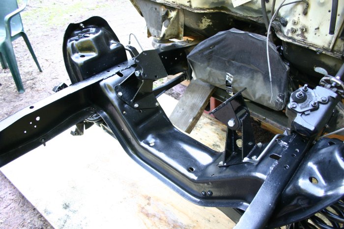
And a more close up one:

Thanks!
-Robroy
Since I was at the project site today I took two more photos of the mounts. I'm probably going overkill by now but I keep thinking that the lighting is better than the previous photos, so here they are:
And a more close up one:
Thanks!
-Robroy
-
robroy
- 100% FORDified!
- Posts: 3768
- Joined: Sun Jul 06, 2008 4:36 pm
- Location: California, Salinas
Re: Upgraded FE motor and transmission mounts from Autofab.com
I mailed John at Autofab this morning and heard back almost immediately.
I asked him about why the passenger's side mount lacks the gusset. He said that they didn't think it needed a gusset because it's significantly shorter than the driver's side mount.
He pretty much left it at that. I figure he has the experience with fabrication to judge this well, and at least we now know that the gusset wasn't left out by mistake!
Robroy
-
robroy
- 100% FORDified!
- Posts: 3768
- Joined: Sun Jul 06, 2008 4:36 pm
- Location: California, Salinas
Re: FE motor and trans' mounts from Autofab; alignment problem!
I finally got the new engine sitting down in these beautiful mounts!
I think there's a problem. The whole engine and transmission combo isn't totally parallel to the frame when sitting in these mounts; it's rotated slightly clockwise (when viewed from above).
This is plain to see when standing right in front of the engine and looking down at the various flat surfaces on the front of the engine (like the front of the harmonic balancer or the front of the water pump flange where the fan mounts).
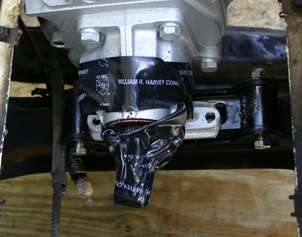
I also measured it. I placed a piece of straight pipe across the frame rails and slid it up against the harmonic balancer, so that it was completely perpendicular to the front of the balancer, as shown in this photo:
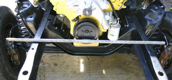
Then I measured the distance between the pipe and the middle of the radiator support mounting hole.
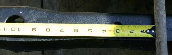
This distance was about 10" on the driver's side:
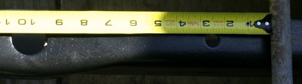
Yet the distance was about 10 and 3/16" on the passenger's side!
I first noticed this when I observed that the transmission was hovering over its mount in a funny way. In this photo you can see how the holes don't line up.
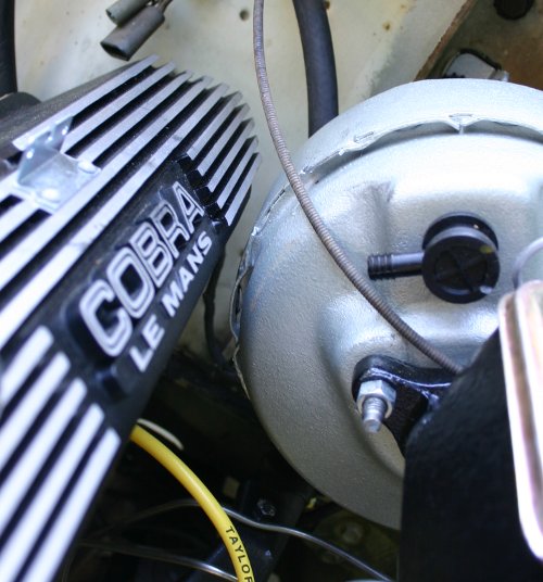
The driver's side valve cover is also a little too close to the brake booster--it would probably to a chore to remove.
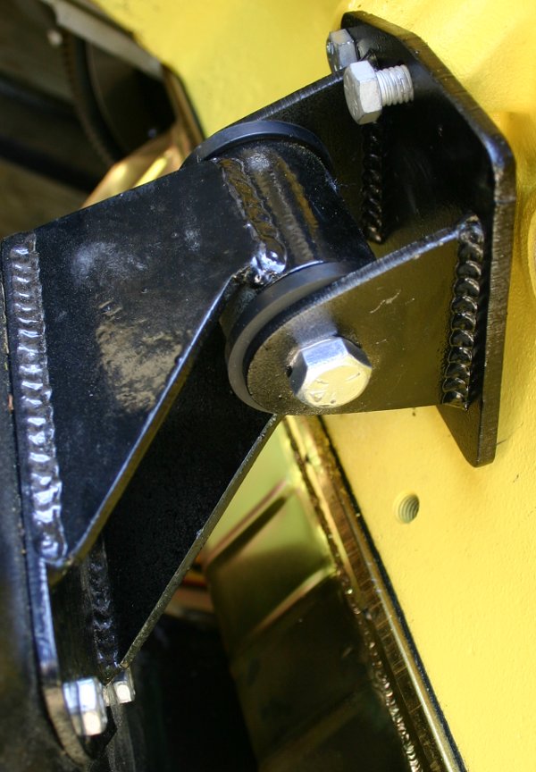
The mounts aren't adjustable, as far as I can tell. Here they are. Note that some of the bolts aren't threaded in all the way, but the mounts are definitely flush with the engine block.
Passenger's side:
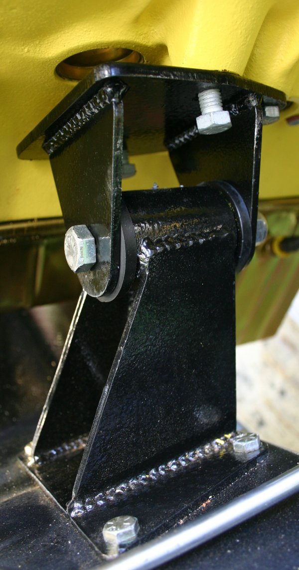
Driver's side:
Based on this new development, could I ask for advice on these questions?
I plan on mailing John at AutoFab to ask for his advice on this issue, but I wanted to hear from you guys also.
Thanks very much for all the guidance!
Robroy
I think there's a problem. The whole engine and transmission combo isn't totally parallel to the frame when sitting in these mounts; it's rotated slightly clockwise (when viewed from above).
This is plain to see when standing right in front of the engine and looking down at the various flat surfaces on the front of the engine (like the front of the harmonic balancer or the front of the water pump flange where the fan mounts).
I also measured it. I placed a piece of straight pipe across the frame rails and slid it up against the harmonic balancer, so that it was completely perpendicular to the front of the balancer, as shown in this photo:
Then I measured the distance between the pipe and the middle of the radiator support mounting hole.
This distance was about 10" on the driver's side:
Yet the distance was about 10 and 3/16" on the passenger's side!
I first noticed this when I observed that the transmission was hovering over its mount in a funny way. In this photo you can see how the holes don't line up.
The driver's side valve cover is also a little too close to the brake booster--it would probably to a chore to remove.
The mounts aren't adjustable, as far as I can tell. Here they are. Note that some of the bolts aren't threaded in all the way, but the mounts are definitely flush with the engine block.
Passenger's side:
Driver's side:
Based on this new development, could I ask for advice on these questions?
- How precisely parallel does the engine/transmission need to be to the frame in a Bumpside?
- Based on my description and the photos, do you think it would work with no issues as-is? Or does it definitely need a modification?
- What would the effect on the driveline be if the transmission output were a little skewed, as shown in the photo?
I plan on mailing John at AutoFab to ask for his advice on this issue, but I wanted to hear from you guys also.
Thanks very much for all the guidance!
Robroy
-
Ranchero50

- Moderator
- Posts: 5799
- Joined: Wed Nov 08, 2006 7:02 pm
- Location: Maryland, Hagerstown
- Contact:
Re: FE motor and trans' mounts from Autofab; alignment problem!
Robroy, this is the fun part of custom...
First step is support the weight of the motor tranny combo with the engine hoist
Loosen the frame to mount bolts
Twist motor tranny so the tranny will engage the crossmember mounts
Tap the base of the mounts (drivers back, pass forward) so the stands will let the motor sit correct.
Tighten frame mounts and unload the motor.
Push the tranny up out of the mount and see what the tranny does. If it still kicks to the side you need to remove one of the stands and slot the crossmember hole with a round file or dremel or even a drill bit if you don't have anything better.
As far as how important is it, not really, but it's an easy fix and you care enough to want it to look 'correct'.
Another thing, put a 4' level across the frame rails and then compare to the same level across the valve covers. You can adjust that with the engine perches too (push the high side perch down and the low side up before tightening the bolts up.
Have fun.
Jamie
'70 F-350 CS Cummins 6BT 10klb truck 64k mile Bahama Blue
Contact me for CNC Dome Lamp Bezels and Ash Tray pulls.
Contact me for CNC Dome Lamp Bezels and Ash Tray pulls.
-
robroy
- 100% FORDified!
- Posts: 3768
- Joined: Sun Jul 06, 2008 4:36 pm
- Location: California, Salinas
Re: FE motor and trans' mounts from Autofab; alignment problem!
Jamie, thanks very much for your high quality reply! I hadn't thought of using up all available slack in the motor mount to frame bolts as a first step, but that makes perfect sense. That's the first thing I'll try this coming Saturday! Thank you!Ranchero50 wrote:Robroy, this is the fun part of custom...
First step is support the weight of the motor tranny combo with the engine hoist
Loosen the frame to mount bolts
Twist motor tranny so the tranny will engage the crossmember mounts
Tap the base of the mounts (drivers back, pass forward) so the stands will let the motor sit correct.
Tighten frame mounts and unload the motor.
Push the tranny up out of the mount and see what the tranny does. If it still kicks to the side you need to remove one of the stands and slot the crossmember hole with a round file or dremel or even a drill bit if you don't have anything better.
Although I can't imagine getting 3/16" of play out of those bolt holes, it may be possible to get 1/16" out of one side and 1/16" out of the other, then calling it good enough (if it really is within 1/16" of being perfect).
OK, great to know!Ranchero50 wrote:As far as how important is it, not really, but it's an easy fix and you care enough to want it to look 'correct'.
I wonder how perfect the alignment of engines from the factory is. I've never paid attention to this before.
Great idea--I hadn't thought of that at all! I'm not sure if the perches are really adjustable in this way though, since as I understand it, the two huge bolts that couple the halfs of the perches together don't actually locate anything. For instance, if I raised a side up, then tightened that big bolt down and released the cherry picker, I don't think that big bolt would be tight enough to keep that side from just slipping down as far as possible. I hope I'm wrong about this!Ranchero50 wrote:Another thing, put a 4' level across the frame rails and then compare to the same level across the valve covers. You can adjust that with the engine perches too (push the high side perch down and the low side up before tightening the bolts up.
Jamie, based on your great reply I have yet more questions:
- If I do need to slot the holes for one of the engine stands, I should put the slot in the base of the stand itself, right (not in the truck frame)?
- So it won't mess up the driveline if the engine alignment is a little skewed? I could imagine it causing the U joint at the transmission yoke to wear out right away. Does the U joint at the transmission yoke correct for all that skew with no issues at all?
- Based on what you've read and the photos, would you say the Autofab mounts are problematic, or is this kind of "hand fitting" completely normal for after market mounts of all types?
- Do these issues often come up with the Ford factory mounts?
Robroy
-
fordman
- 100% FORDified!
- Posts: 22330
- Joined: Sun Aug 28, 2005 8:17 pm
- Location: Kansas, Ottawa
- Contact:
Re: Upgraded FE motor mounts (including autofab.com).
i figured there might be a difference in the trans moutn for the c6 vs the t18. they do have different moutn hole that are offset on the t18 and the c6 holes are center in the orginal mount.fordman wrote:unless his c6 mount is slotted where it bolts onto the transmission. it will be hard to put in if at all. plus it will probably be tweaked if it goes in. this is just an opinion. not a fact
as far as the factory engine mounts i have never seen that problem.
-
Happy_Camper

- Preferred User

- Posts: 341
- Joined: Thu Oct 23, 2008 10:46 pm
Re: FE motor and trans' mounts from Autofab; alignment problem!
I can't remember an engine installation, that I haven't followed a similar procedure to what Jamie listed above.
I'm a bit of a "perfectionist" when it comes to drivetrain alignment from dealing with cars that use short driveshafts.
Like Jamie said, it's probably not as critical on a truck with a two piece driveline, but it's worth getting it as close as you reasonably can.
Looking good!
I'm a bit of a "perfectionist" when it comes to drivetrain alignment from dealing with cars that use short driveshafts.
Like Jamie said, it's probably not as critical on a truck with a two piece driveline, but it's worth getting it as close as you reasonably can.
Looking good!
Scott
1972 F250 Explorer C/S, 390-2V, Dual exhaust, C6, Goose neck ball in bed
New and improved with Tilt Wheel, Intermittent Wipers, 2005 Bench seat and 5th wheel camper!...
Life is *very* good!

1972 F250 Explorer C/S, 390-2V, Dual exhaust, C6, Goose neck ball in bed
New and improved with Tilt Wheel, Intermittent Wipers, 2005 Bench seat and 5th wheel camper!...
Life is *very* good!
-
robroy
- 100% FORDified!
- Posts: 3768
- Joined: Sun Jul 06, 2008 4:36 pm
- Location: California, Salinas
Re: Upgraded FE motor mounts (including autofab.com).
Fordman and Scott, thanks for replying!
So do you think the U joints are supposed to absorb the skew of an engine like mine in its current orientation?
Thanks again Fordman and Scott!
Robroy
Thanks for reminding me about this! Now that both mounts are nearby I should place them next to each other and see if the slots are really in the same places or not. I think I already did this exercise a while back and determined that they were compatible but I should do it again to be sure. At least I should do this before spending a huge amount of effort making it work.fordman wrote:i figured there might be a difference in the trans moutn for the c6 vs the t18. they do have different moutn hole that are offset on the t18 and the c6 holes are center in the orginal mount.fordman wrote:unless his c6 mount is slotted where it bolts onto the transmission. it will be hard to put in if at all. plus it will probably be tweaked if it goes in. this is just an opinion. not a fact
Thanks Scott!!! It's good to know that this is a common problem, because that makes me think that these fancy engine stands aren't defective in any way. It sounds like a standard issue to run in to during an engine install. Especially since I completely tightened down the engine stands to the frame before dropping the engine in!Happy_Camper wrote:I can't remember an engine installation, that I haven't followed a similar procedure to what Jamie listed above.
I'm a bit of a "perfectionist" when it comes to drivetrain alignment from dealing with cars that use short driveshafts.
Like Jamie said, it's probably not as critical on a truck with a two piece driveline, but it's worth getting it as close as you reasonably can.
Looking good!
So do you think the U joints are supposed to absorb the skew of an engine like mine in its current orientation?
Thanks again Fordman and Scott!
Robroy
-
Ranchero50
- Moderator
- Posts: 5799
- Joined: Wed Nov 08, 2006 7:02 pm
- Location: Maryland, Hagerstown
- Contact:
Re: FE motor and trans' mounts from Autofab; alignment problem!
Do I think the mounts are the problem? Not really, the problem is you unbolted and replaced the mounts, aftermarket and stockers will give the same results.
For the crank centerline rotation, look at the crank from the front of the truck, look at the crossmember mounts from the same point. Swing an arc from one mount to the other with the pivot point being the center of the crank. See how loosening both sets of crossmember bolts will allow you to rotate the motor slightly? I set the tranny in and pick up the motor slightly by the water pump snout (not the shaft) so I can rotate the motor on the crank centerline to get it to sit level. Not a big deal, just loosen all the mount bolts, level the motor then tighten all the bolts except the long one that ties the mount halves together, then let the motor rest on the mounts and recheck everything before tightening the long bolts. That way the motor won't settle once the job is done and be crooked again in a week or two...
As the other guys say this is the way every engine install is if you care enough to do it right. As for the U joints they are doing their job. There's a good bit of theory about the angle, the 4x4 guys run into problems where you need some angle on each side or it'll vibrate, once again not something you are going to have with this setup so don't sweat it so much.
Jamie
'70 F-350 CS Cummins 6BT 10klb truck 64k mile Bahama Blue
Contact me for CNC Dome Lamp Bezels and Ash Tray pulls.
Contact me for CNC Dome Lamp Bezels and Ash Tray pulls.
-
averagef250

- 100% FORDified!
- Posts: 4387
- Joined: Fri Mar 17, 2006 12:58 am
- Location: Oregon, Beavercreek
Re: FE motor and trans' mounts from Autofab; alignment problem!
I completely agree with Jamie and Scott. It's surprising how much the small amount of play in the mount bolts can effect how things fit together and the final appearance.
I like to use one of those load leveler adjusters hooked up left-right across the front of the engine. With the mount bolts loose and the weight of the engine on the cherry picker/crane you can try to adjust the engine to sit where you want it to. Sometimes it's a bear and 40 years of use has tweaked something in the trucks frame or you've just got parts that were made a little off.
I like to use one of those load leveler adjusters hooked up left-right across the front of the engine. With the mount bolts loose and the weight of the engine on the cherry picker/crane you can try to adjust the engine to sit where you want it to. Sometimes it's a bear and 40 years of use has tweaked something in the trucks frame or you've just got parts that were made a little off.
1970 F-250 4x4 original Willock swivel frame chassis '93 5.9 Cummins/Getrag/NP205/HP60/D70
-
fordman
- 100% FORDified!
- Posts: 22330
- Joined: Sun Aug 28, 2005 8:17 pm
- Location: Kansas, Ottawa
- Contact:
Re: FE motor and trans' mounts from Autofab; alignment problem!
well i have to retort on what i said. i installed and engine and trans today with no dody on the truck at all. so i had all kinds of room to work. what happened was that i had to pull the transmission toward the drivers side to get it to line up with the crossmember. and the crossmember wasnt bolted in yet either so when i was done it pushed itself back towards the passenger side. ok now since i made the mistake of not moving the mounts back to the fe position since the truck had a 6 cyl in ti i get to do the whole job over again tomorrow. no wonder the driveshaft and crossmember didn't line up with the transmission and the frame bolt holes. give yours a try adjusting your mounts it may help it all work out.
-
robroy
- 100% FORDified!
- Posts: 3768
- Joined: Sun Jul 06, 2008 4:36 pm
- Location: California, Salinas
Re: FE motor and trans' mounts from Autofab; alignment problem!
Jamie, Dustin, and Fordman, thanks very much for replying!
And by swinging an arc, do you mean using a piece of string, like a compass? Or were you suggesting that I merely imagine this as a method for understanding how the engine could tilt in that manner?
If I'm measuring the distance between the bolts that hold the engine stands to the frame and the center of the crankshaft, I'm not sure how this would be different depending on how the engine block is rotated (rotated in the sense of the measurement using the carpenter's level). It seems to me that this measurement would remain constant regardless of the attitude of the engine. I'm probably just not understanding your instructions. Thanks for being so patient--I'm a beginner!
Thanks guys for your patience and the great advice. If anybody's willing and able to explain it, I'd be very curious to hear more about how these engine+transmission to frame alignment issues can impact the operation of the engine or smooth performance of the drivetrain. For instance, if the rotation of the engine+transmission from a bird's eye view isn't critical (if it's not critical for that to be at 12 o'clock sharp), is all the magic that allows that found in the U joint at the transmission yoke?
Thanks again Jamie, Dustin, and Fordman!
Robroy
OK, thanks!Ranchero50 wrote:Do I think the mounts are the problem? Not really, the problem is you unbolted and replaced the mounts, aftermarket and stockers will give the same results.
I'm trying to imagine this but not fully following it yet. Is this a method for adjusting the the attitude I'd be measuring by resting a level over the valve covers and comparing it to level reading when resting across the frame rails?Ranchero50 wrote:For the crank centerline rotation, look at the crank from the front of the truck, look at the crossmember mounts from the same point. Swing an arc from one mount to the other with the pivot point being the center of the crank. See how loosening both sets of crossmember bolts will allow you to rotate the motor slightly?
And by swinging an arc, do you mean using a piece of string, like a compass? Or were you suggesting that I merely imagine this as a method for understanding how the engine could tilt in that manner?
If I'm measuring the distance between the bolts that hold the engine stands to the frame and the center of the crankshaft, I'm not sure how this would be different depending on how the engine block is rotated (rotated in the sense of the measurement using the carpenter's level). It seems to me that this measurement would remain constant regardless of the attitude of the engine. I'm probably just not understanding your instructions. Thanks for being so patient--I'm a beginner!
OK! This part I think I understand and I could give it a whirl.Ranchero50 wrote:I set the tranny in and pick up the motor slightly by the water pump snout (not the shaft) so I can rotate the motor on the crank centerline to get it to sit level. Not a big deal, just loosen all the mount bolts, level the motor then tighten all the bolts except the long one that ties the mount halves together, then let the motor rest on the mounts and recheck everything before tightening the long bolts. That way the motor won't settle once the job is done and be crooked again in a week or two...
Great; that's good to know! Thanks!Ranchero50 wrote:As the other guys say this is the way every engine install is if you care enough to do it right.
OK, thanks! You know, since I'll be spinning this driveline at 5,500 RPM or even higher, I'm curious to hear more about this! Why is it that this is unimportant with this particular driveline? Is it because of the center bearing, somehow? Or something about the yokes and U joints?Ranchero50 wrote:As for the U joints they are doing their job. There's a good bit of theory about the angle, the 4x4 guys run into problems where you need some angle on each side or it'll vibrate, once again not something you are going to have with this setup so don't sweat it so much.
That's great to know!averagef250 wrote:I completely agree with Jamie and Scott. It's surprising how much the small amount of play in the mount bolts can effect how things fit together and the final appearance.
OK, that sounds like a wise suggestion--it sounds like it would be easier to adjust this particular alignment with the leveler than trying to nudge it by hand. I'm not very good at manipulating this 850lb+ package by hand! Thanks for this tip!averagef250 wrote:I like to use one of those load leveler adjusters hooked up left-right across the front of the engine. With the mount bolts loose and the weight of the engine on the cherry picker/crane you can try to adjust the engine to sit where you want it to. Sometimes it's a bear and 40 years of use has tweaked something in the trucks frame or you've just got parts that were made a little off.
Sounds like an adventure there!fordman wrote:well i have to retort on what i said. i installed and engine and trans today with no dody on the truck at all. so i had all kinds of room to work. what happened was that i had to pull the transmission toward the drivers side to get it to line up with the crossmember. and the crossmember wasnt bolted in yet either so when i was done it pushed itself back towards the passenger side. ok now since i made the mistake of not moving the mounts back to the fe position since the truck had a 6 cyl in ti i get to do the whole job over again tomorrow. no wonder the driveshaft and crossmember didn't line up with the transmission and the frame bolt holes. give yours a try adjusting your mounts it may help it all work out.
Thanks guys for your patience and the great advice. If anybody's willing and able to explain it, I'd be very curious to hear more about how these engine+transmission to frame alignment issues can impact the operation of the engine or smooth performance of the drivetrain. For instance, if the rotation of the engine+transmission from a bird's eye view isn't critical (if it's not critical for that to be at 12 o'clock sharp), is all the magic that allows that found in the U joint at the transmission yoke?
Thanks again Jamie, Dustin, and Fordman!
Robroy