"Doorjam13"]1972
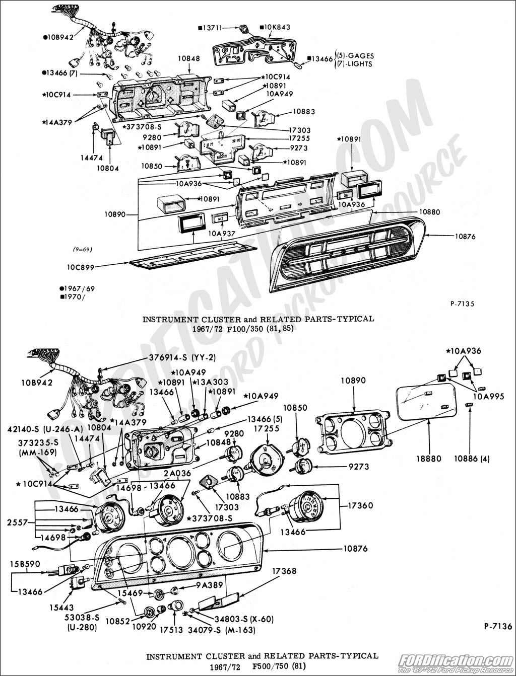
Your 1972 will have the printed circuit board on the back like part number 10K843 in the top image on this page, (unless someone has changed out the panel which is doubtful):
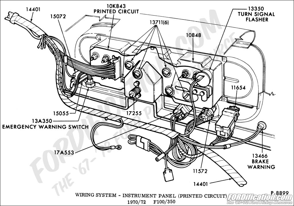
Here's another good image of what your looking at. The harness plugs into the printed circuit board and powers the lamps, (part number 13711 of which there are six of them). A lot of times these bulbs are the issue and are also easily tested (also using a voltage meter-a crummy "test probe" will also be useless to test the bulbs):
You really first need to get a cheap voltage meter which can be bought anywhere for less than $10.00 like this one-and easily learn to read it here on the forum, (not a crummy test lamp that destroys your wiring harness by piercing the wiring insulation) and test for "voltage" (not just "power) to the instrument panel (as once again it gets "voltage" from the headlight switch rheostat) and you need to know exactly what it is getting :
https://www.harborfreight.com/7-functio ... 90899.html
Once you've determined the voltage from the headlight switch rheostat is correct, (should be anywhere from 5 VDC to 12 VDC) then you start testing the "sockets" on your instrument panel circuit board. You need to test for voltage on wire #19 A/B in this image (which is the blue with red stripe wire in the harness that feeds the instrument panel).

Jeff
http://www.fordification.com/forum/view ... 22&t=46251
SOLD-71 F-350 dually flatbed, 302 / .030 over V-8 with a "baby"C-6, B & M truckshifter, Dana70/4.11 ratio, intermittent wipers, tilt steering, full LED lighting on the flat bed, and no stereo yet (this way I can hear the rattles to diagnose)! SOLD!
Many Ford bumps / one 76' EB / and several dents through the years.
A lot of "oddball" Ford parts collected from working on them for 34 years now!
2008 Ford Escape 4 x 4
