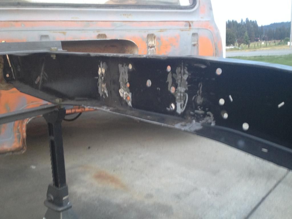
I got the inside of the frame rails all cleaned up by removed the remainder of the crossmember left over from cutting the middle section out with a sawzall. I did all of my cutting inside the frame rails using at 4 1/2" grinder, a jig saw with the base plate removed and a hammer.
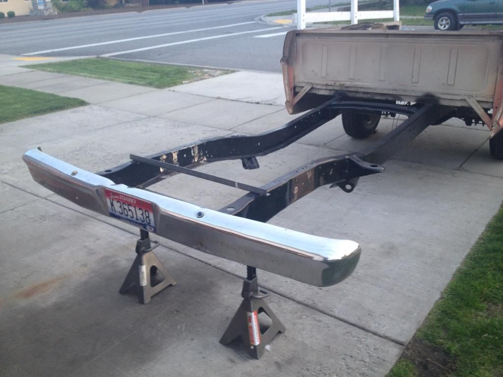
Then I bolted up my bumper just to make sure the frame hadn't moved at all (which it had not):
Then after re-measuring and double checking for my center line about 300 times I drilled out 3/4" holes on the bottom of the frame where my alignment pins were located on the crown vic k-frame, set the crown vic in place and drilled my 4 holes from the mounting bolts.
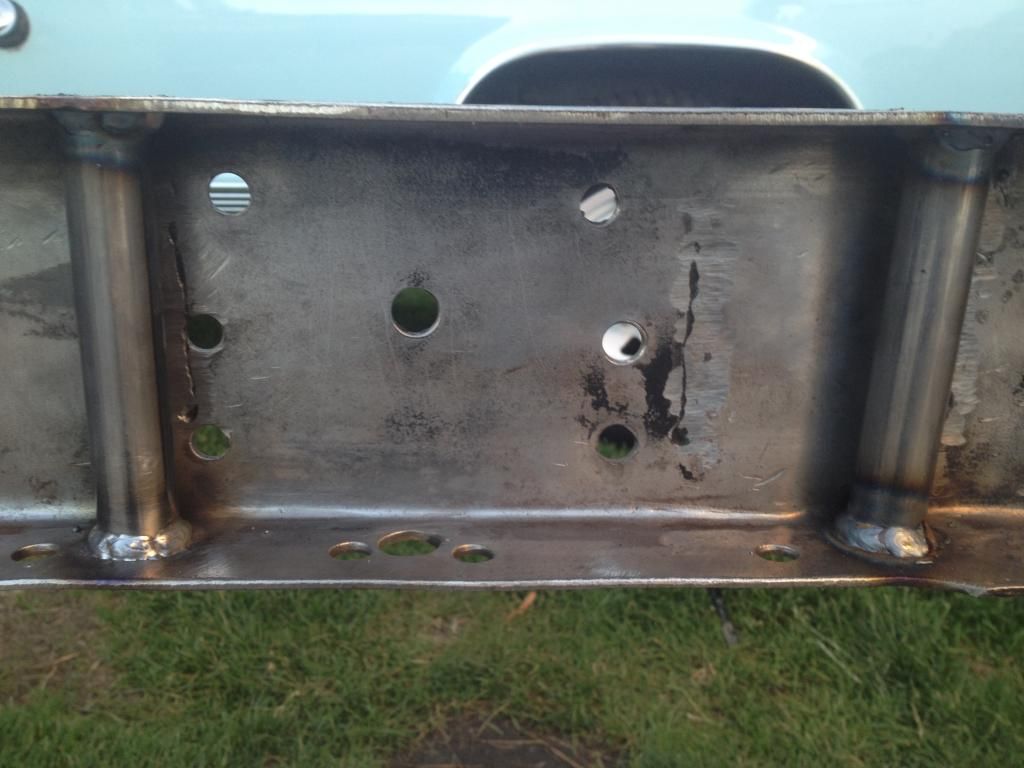
Tip: Double check your frame and make your own measurements but I found that my centerline on my frame was centered between two small holes on the bottom of my frame. Also I found that the center line was the center of the coil spring/shock towers. I measured this before removing the stock suspension parts from the frame. I used a square and laser to transfer my center line marks to the bottom of the frame and then realized all I had to do was measure between the two small holes on the bottom of the frame. Like I said you may want to double check but I thought I'd throw that out there since I hadn't read it anywhere while researching my install process. You can see the holes I'm talking about in the pic above ^
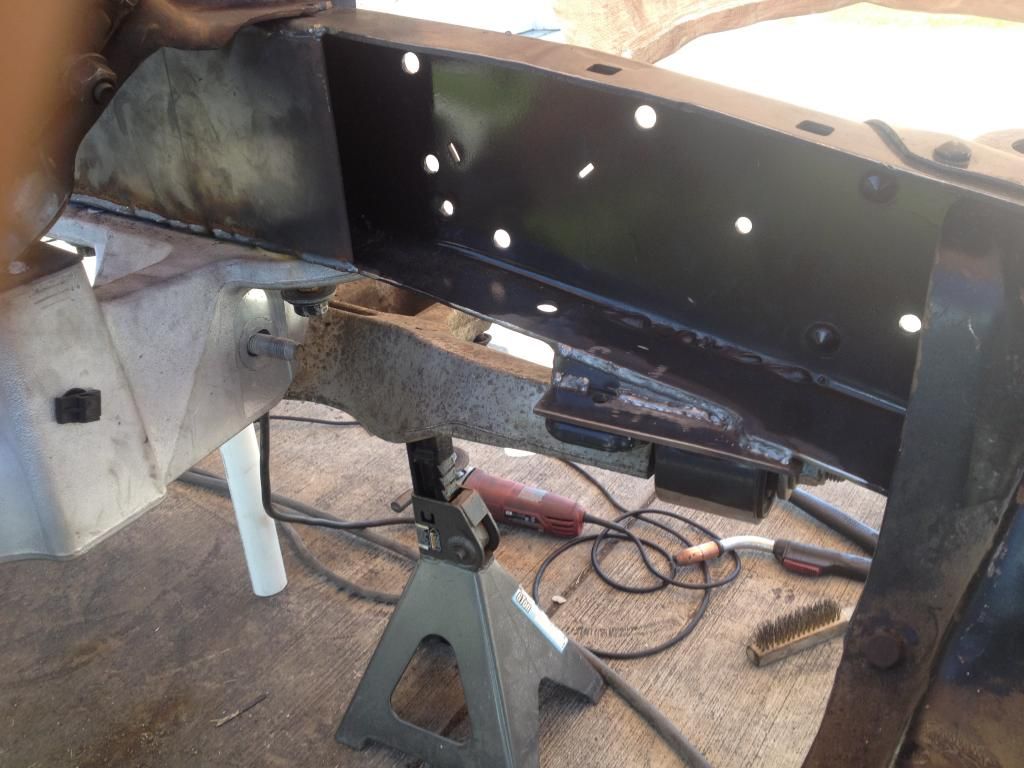
Next I removed the crown vic k-frame and welded in some 120 wall tubing to re-enforce the frame where the mounting bolts go through:
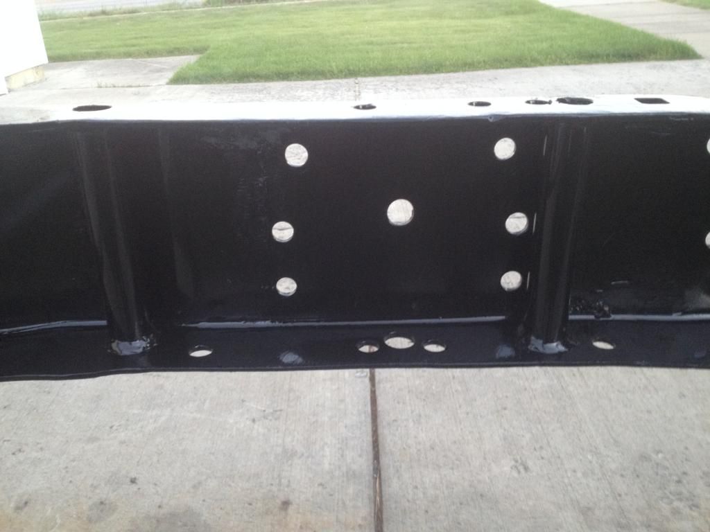
And painted the inside of the frame:
Here's an important step that I haven't seen anyone post about yet:
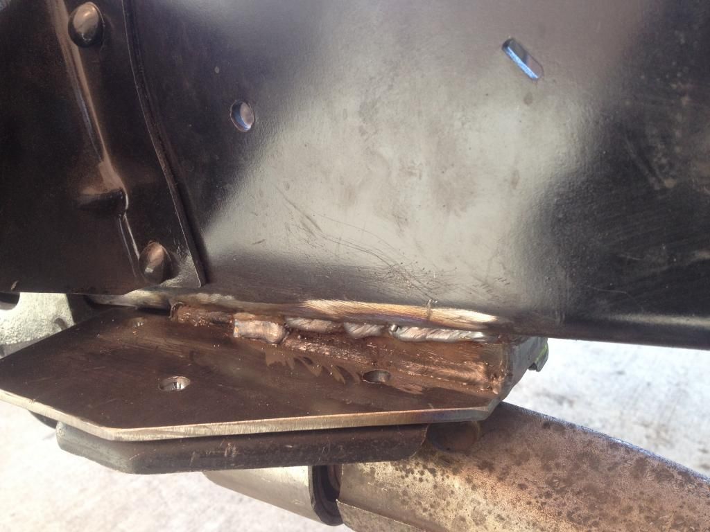
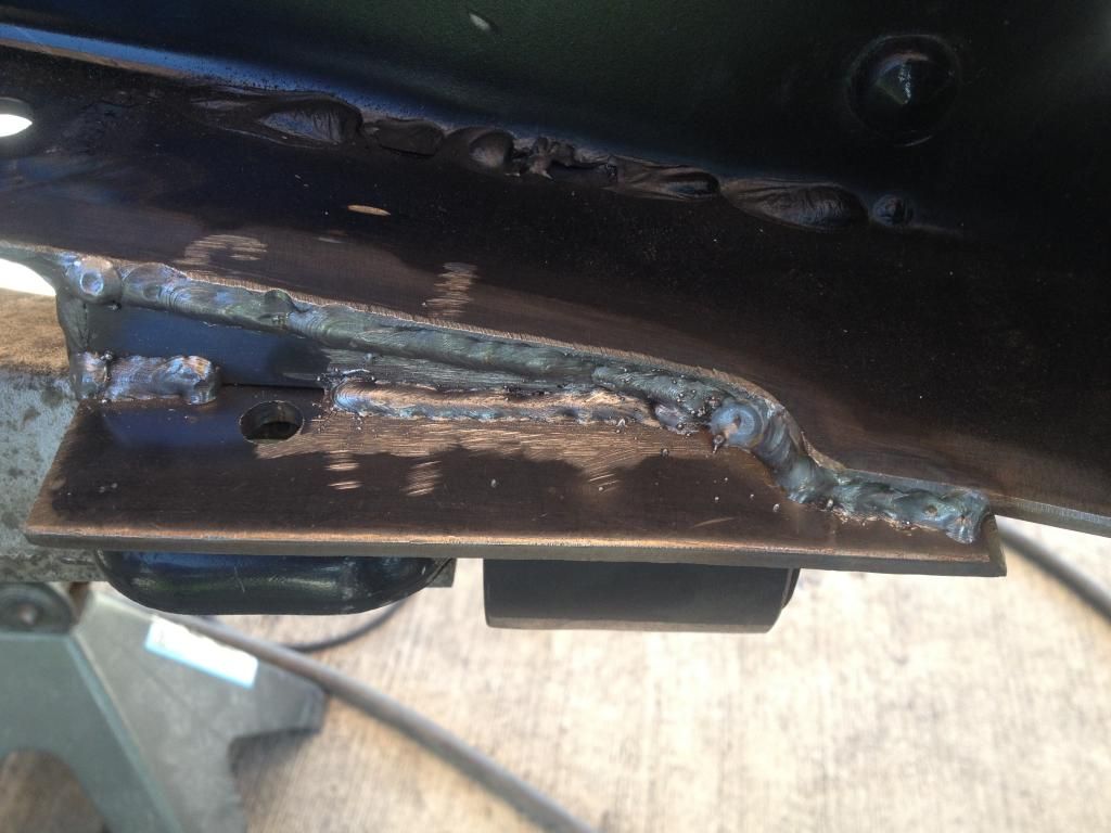
On the crown vic the lower control arm mounts to the frame at an angle. It doesn't sit parallel to the ground like our trucks once it's mounted. This is important because of the way the bushing is clocked on the plate. I cut the tubing/bushing off of the mounting plate and re-clocked if so that the slotted hole would be parallel to the ground when welded up to the frame. This way when I want to adjust my camber and caster the rear of the control arm is only moving side to side and not up and down in the mount. This will also keep the control arm in place instead of it trying to ride up and in from the weight of the vehicle:
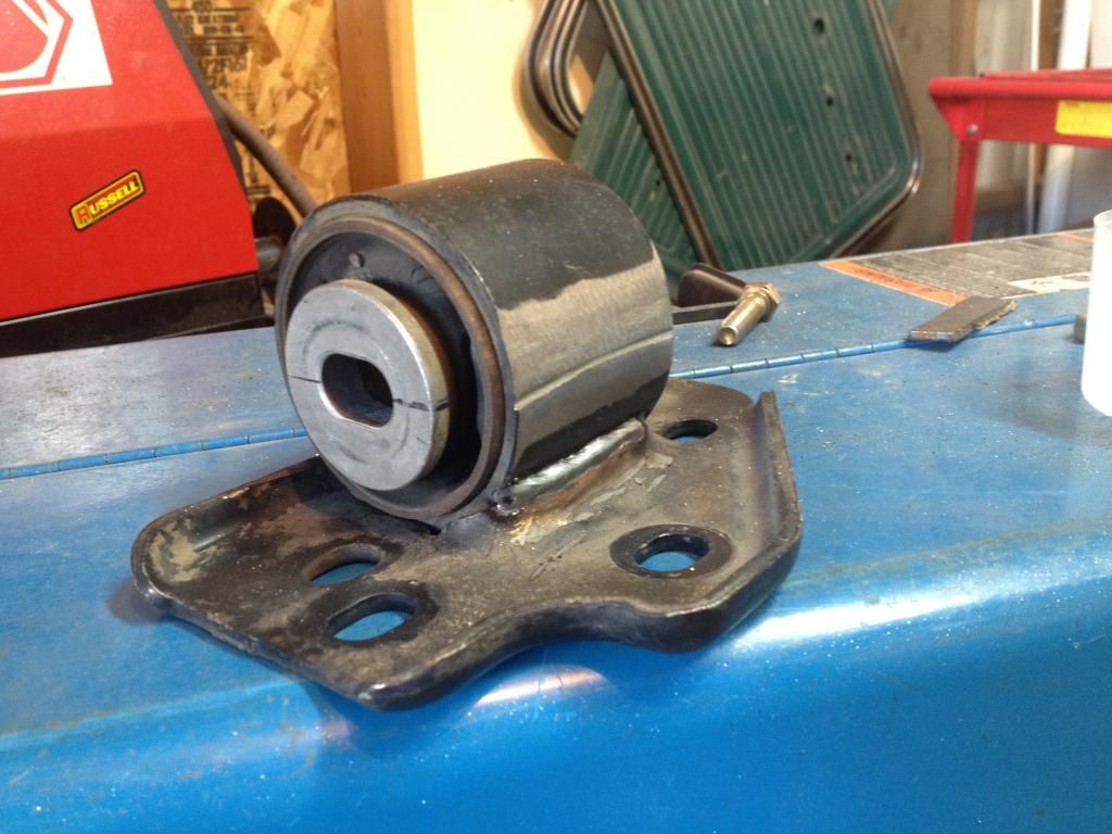
You can see the cut line in the tubing where it was welded to the plate before.
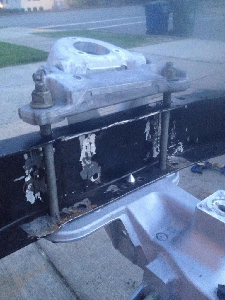
Next I bolted the crown vic in place with the lower conrol arms installed and built a rear mounting plate. You can also see in this picture, the spacer i used between the frame and the upper mount for the k-frame. It is a piece of 1 1/2" x 5/8" aluminum flat bar cut to length and drilled for the mounting bolts to go through. It looks nice and clean. I built the mounting plates from 3/16" steel plate.
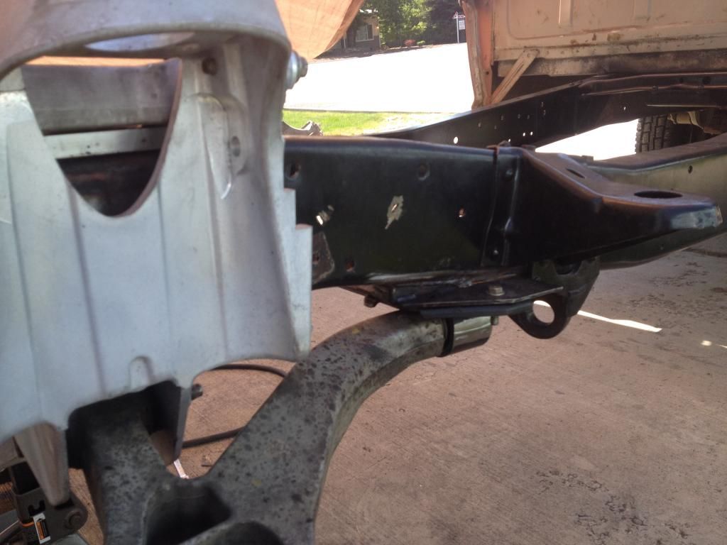
Also got the frame boxed in and painted
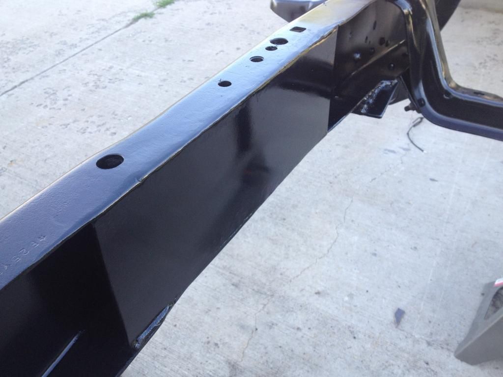
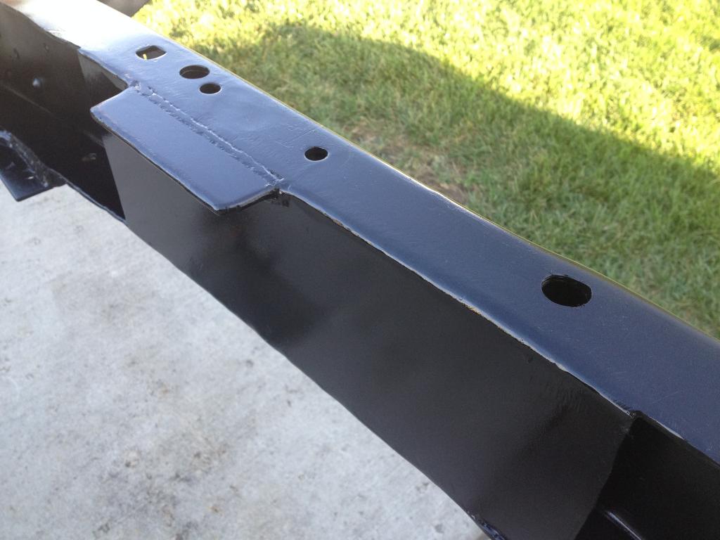
This is what my driver's side motor mount pedestal will be bolted to. I'm modified my factory motor mounts to fit and will make a post to show that process next once I have them finished up. This is a piece of 3/16" welded to the inside of the top of the frame (extends all the way to the inside corner). Then I notched the boxing plate around it and welded the box to it with another piece of 3/16" welded on top. It extends out about 1 1/2" off the frame:
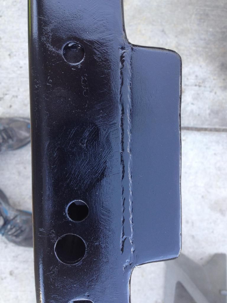
I did this to keep a nice clean look on top of the frame with my flat bar and it will also allow me to remove the mounts if needed without unbolting the suspension.
And the frame is painted and ready to re-assemble:
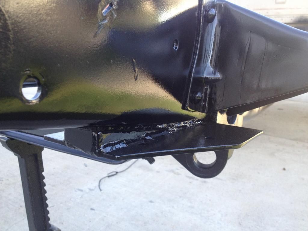
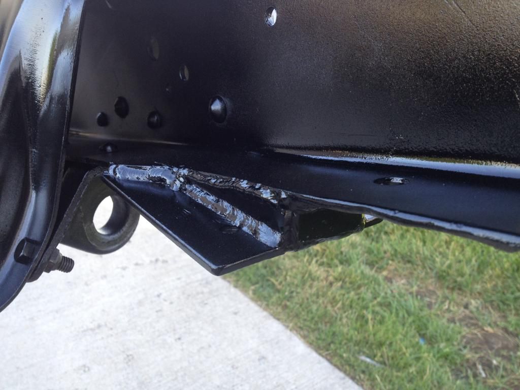
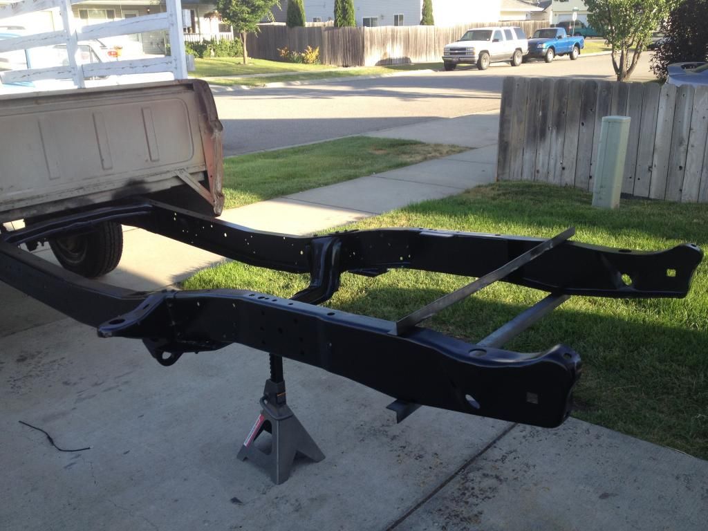
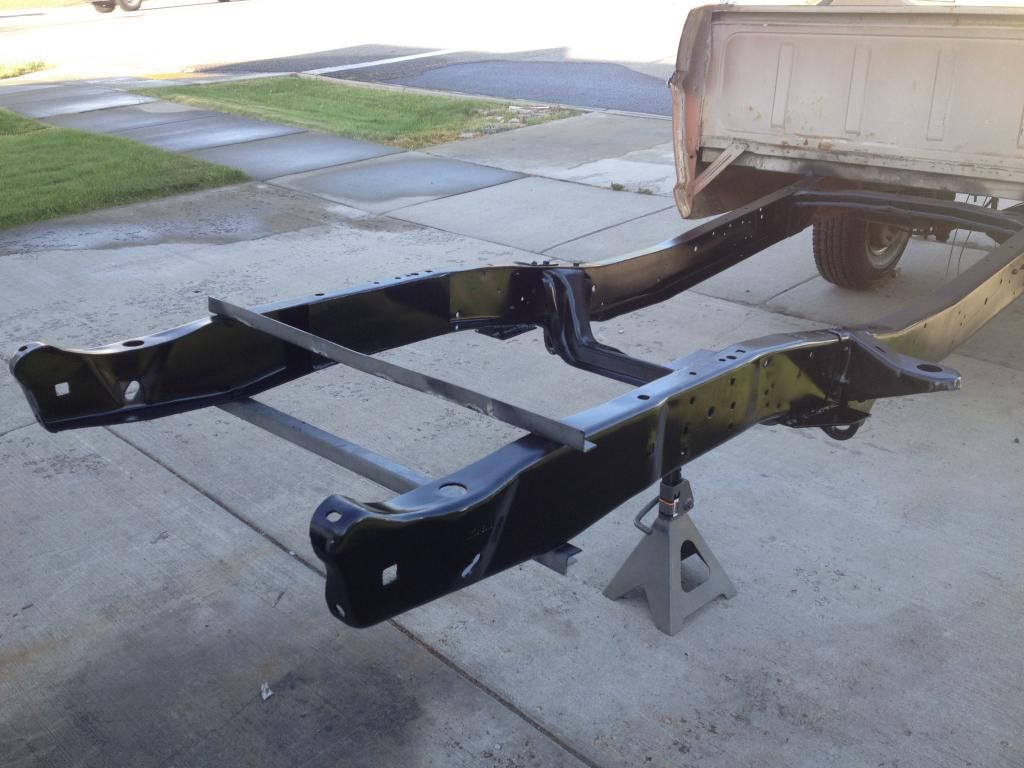
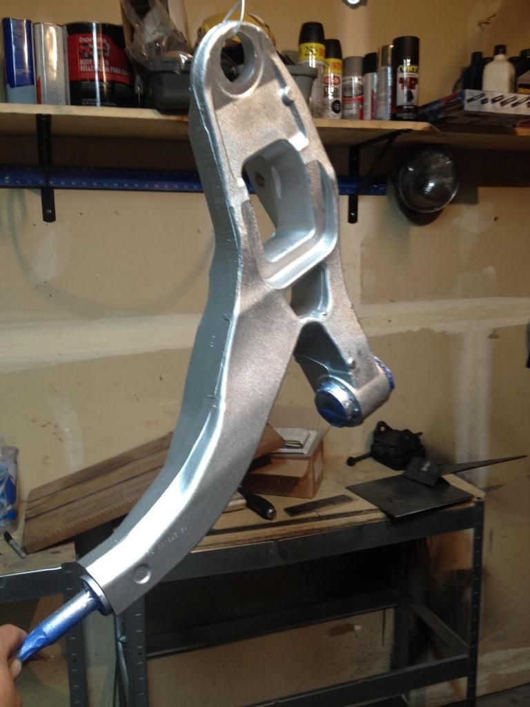
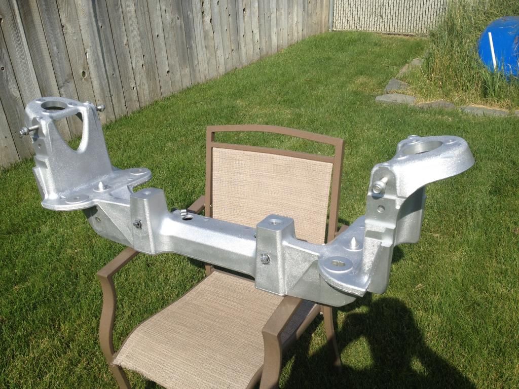
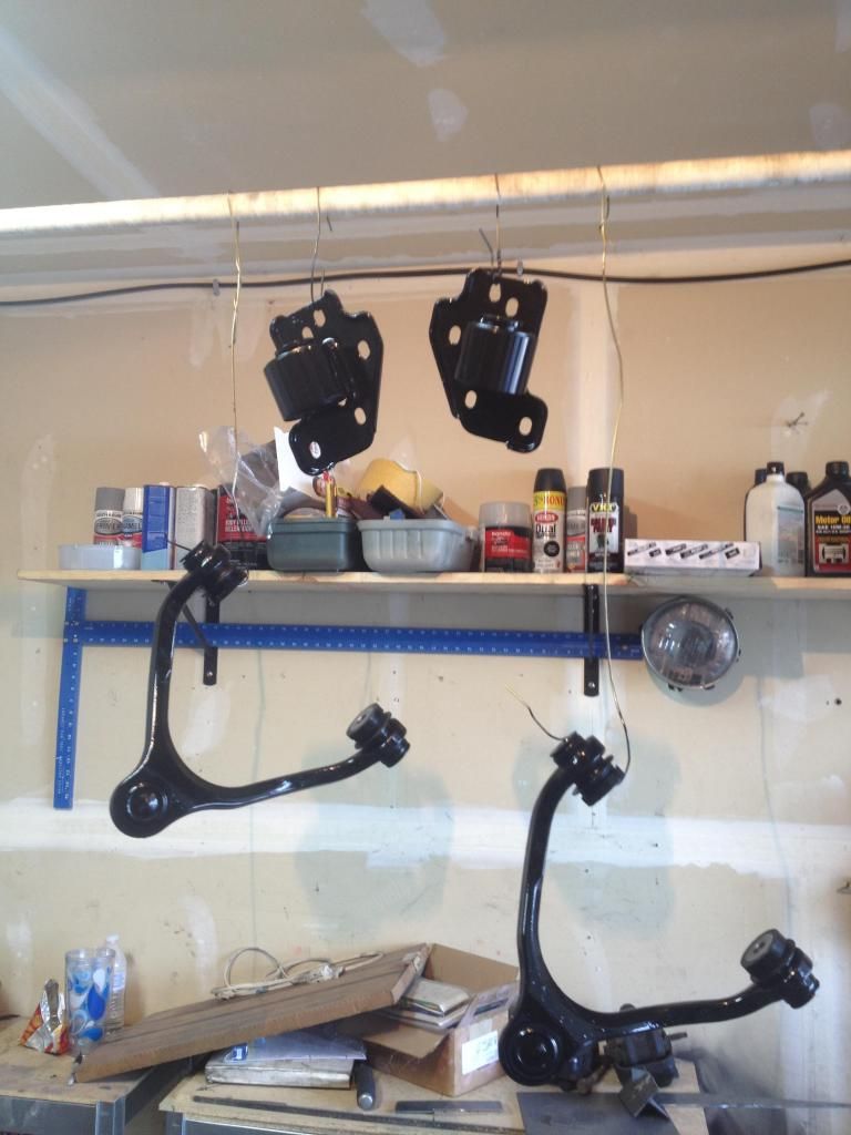
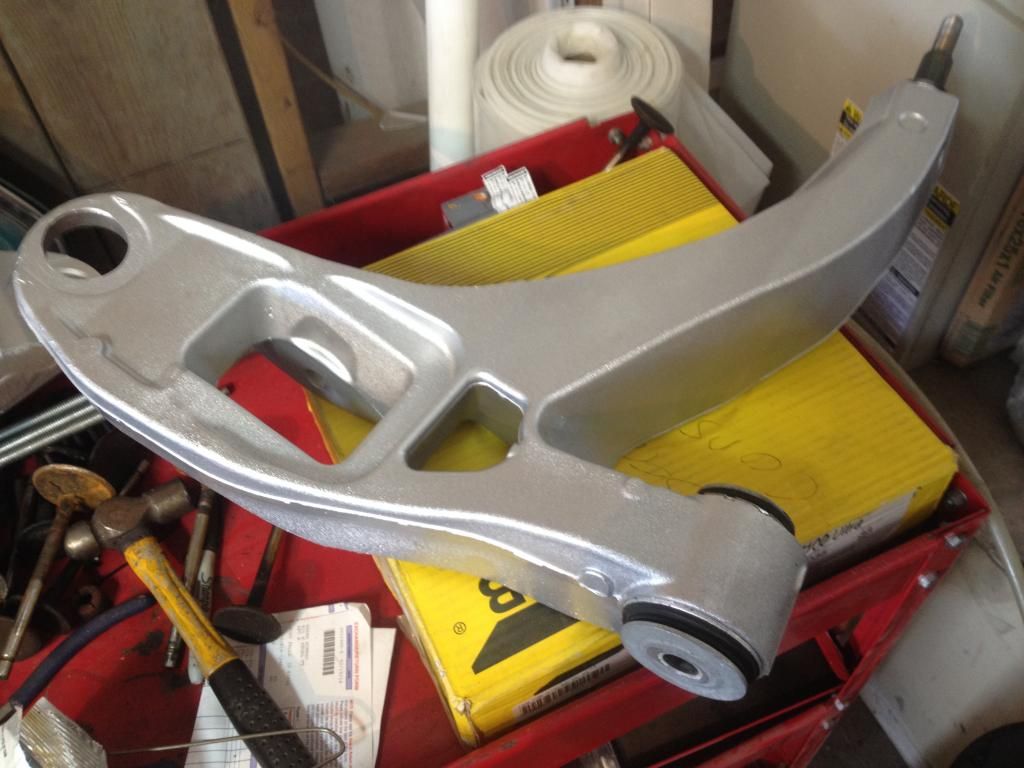
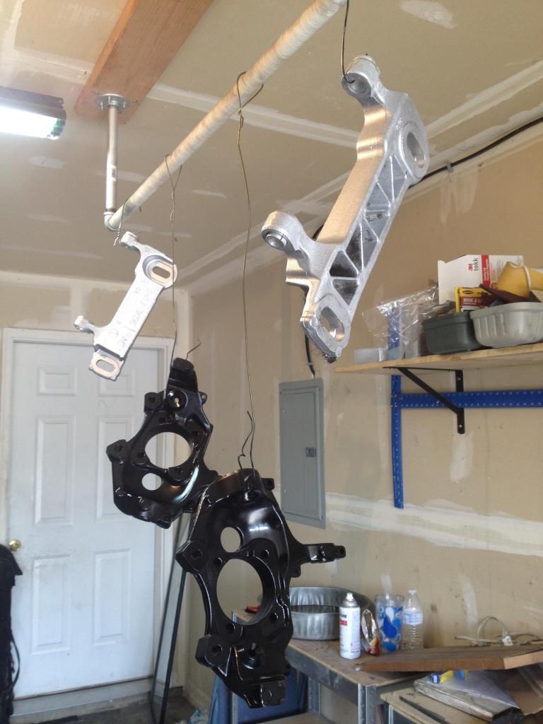
Next up I'll be cleaning up, painting, and installing the front steering/suspension parts. Here's a preview:
