OK, here's a quick diagram I just whipped up of the F600 instrument panel connector:
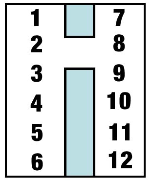
Position 1 - black - IPVR ground
Position 2 - light green w/white stripe - left turn signal indicator
Position 3 - orange - fuel gauge (FULL side)
Position 4 - black w/green stripe- IGN tab of IPVR
Position 5 - white w/red stripe - oil pressure gauge (high side)
Position 6 - light blue w/red stripe - gauge illumination
Position 7 - NOT USED
Position 8 - white w/blue stripe - right turn signal indicator
Position 9 - green w/black stripe - hi-beam indicator
Position 10 - red w/white stripe - temperature gauge (high side)
Position 11 - yellow - ammeter (charge side)
Position 12 - red - ammeter (discharge side)
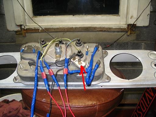
So....to answer your question about which wires to go the IPVR:
There's a black wire which comes from Position 1 in the connector to the IGN tab of the IPVR. A black wire w/white stripe goes from the opposite IPVR tab to the EMPTY stud of the fuel gauge, which then goes to COLD side of the Temperature gauge, which then goes to the LOW side of the oil pressure gauge.
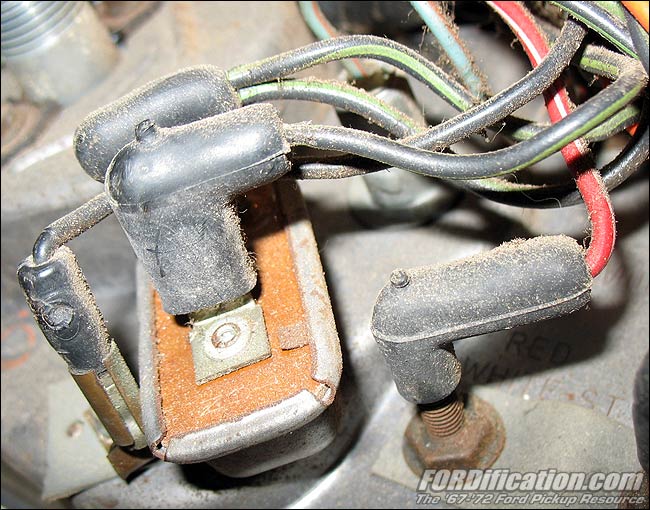
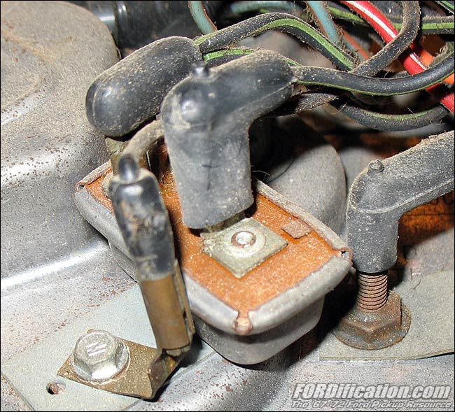
Here's a view taken after cutting the harness wrap.
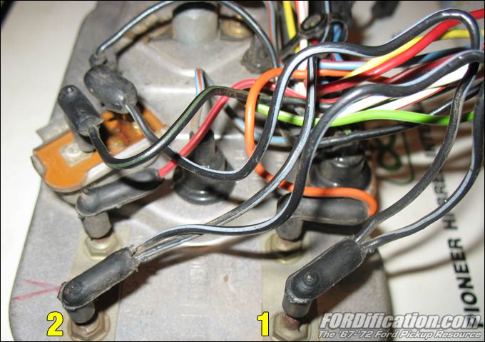
You can see how the black wire w/white stripe goes from the IPVR to the fuel gauge (yellow '1'), then to the temperature gauge (yellow '2') and then across the instrument panel to the oil pressure gauge (not visible).
Hope this helps.


